Eaton PROFIBUS-DP EZ204-DP User Manual
Browse online or download User Manual for Networking Eaton PROFIBUS-DP EZ204-DP. Eaton PROFIBUS-DP EZ204-DP User manual
- Page / 300
- Table of contents
- BOOKMARKS
- 1-888-55-66342 1
- Warning! 3
- Dangerous electrical voltage! 3
- Contents 5
- About This Manual 13
- Overview 16
- ANSI or EZ format 18
- MN05013003E16 20
- EZ xxx-xx-xxx 21
- MN05013003E18 22
- Main menu 23
- EZ500 or EZ700 System 23
- (only on devices with clock) 24
- EZ Status display 24
- Advanced Status display 25
- EZ LED display 25
- Menu structure 26
- MN05013003E24 28
- EZ System menu 29
- DEL and ALT 29
- System menu 30
- YEAR 2004 32
- HH:MM 14:23 32
- DD.MM 17.03 32
- 2Installation 33
- Installation 34
- Mounting 35
- Terminals 37
- MN05013003E38 42
- Connecting the inputs 43
- 100 nF/275 V h 45
- Figure 14: EZ with EZ256-HCI 46
- EZ…-DC-.D 47
- MN05013003E46 50
- MN05013003E48 52
- Connecting the outputs 55
- Connecting relay outputs 56
- EZ512-..-R 56
- EZ7..-..-R.. and EZ202-RE 56
- Connecting transistor outputs 58
- EZ512-..-T 58
- EZ7..-..-T 58
- MN05013003E56 60
- Expanding inputs/outputs 61
- Switching on 65
- 3 Commissioning 65
- Commissioning 66
- EZ operating modes 67
- 69
- MO 02:00 69
- .......STOP 69
- 4 Wiring with EZ 77
- Operation of EZ 79
- MN05013003E76 80
- Relay, function relays 81
- : :1…:8 :1…:8 – 82
- Y Y1…Y8 Y1…Y8 – 82
- Z Z1…Z3 Z1…Z3 – 82
- I2u------ÄQ4 85
- I1 to I2 in the 87
- I3 from make to break 88
- J section 100
- I5-------CC1 101
- I6-------RC1 101
- C1-------TT1 101
- T1-------ÄQ1 101
- Wiring with EZ 102
- Function relays 103
- MN05013003E104 108
- A8-------ÄQ3 113
- First operating state 117
- Counters 119
- MN05013003E116 120
- S 00000 120
- C with setpoint value 122
- = 0.5 × 127
- Contact has not switched 129
- Contact has switched 129
- Actual value (0153) 129
- Text display 139
- Ä, Å, è, ^, ä 139
- D1 to D16 139
- 7-day time switch 145
- Operating hours counter 151
- Timing relays 155
- I1 Time setpoint 1: 155
- MN05013003E152 156
- MN05013003E156 160
- MN05013003E158 162
- MN05013003E160 164
- Timing relay, single pulse 165
- MN05013003E162 166
- :1 to :8 170
- Ä:1 to Ä:8 170
- : of the 171
- Year time switch 173
- Master reset 181
- Basic circuits 183
- Example circuits 191
- Storage positions 192
- PULSE VALUE RESET 192
- 5 EZ Settings 203
- EZ Settings 204
- Password protection 205
- DELETE ? 209
- Changing parameters 211
- XSelect the RULE menu 219
- XPress the OK button 219
- ÍÚ Select required value 221
- Startup behavior 225
- RUN MODE EZ is in STOP mode 226
- RUN MODEå EZ is in RUN mode 226
- Setting the cycle time 229
- 6Inside EZ 235
- Inside EZ 236
- EZ circuit diagram cycle 237
- Figure 87: On and off delays 241
- Expanding EZ700 243
- Figure 89: Remove the cover 247
- Memory card 249
- INVALID PROG 253
- 7 What Happens If ...? 255
- What Happens If ...? 256
- Dimensions 259
- MN05013003E256 260
- Appendix 262
- Technical Data 263
- Available function relays 278
- Names of relays 279
- Names of function relay 279
- Glossary 281
- MN05013003E282 286
- MN05013003E284 288
- MN05013003E286 290
- MN05013003E288 292
- MN05013003E290 294
- MN05013003E292 296
- MN05013003E294 298
Summary of Contents
For more information visit: www.EatonElectrical.comMN05013003EEZ500/700 SeriesUser ManualApril 2005EZ500_700.book Page 1 Tuesday, May 3, 2005 5:15
For more information visit: www.EatonElectrical.com MN05013003E6Activating and deactivating the P buttons 220– Activating the P buttons 220– Functio
For more information visit: www.EatonElectrical.comWiring with EZMN05013003E96A function relay is started via its relay coil or by evaluating a parame
Function relaysFor more information visit: www.EatonElectrical.comMN05013003E 97Figure 46: Hard-wiring with relaysThe wiring of the EZ relay looks as
For more information visit: www.EatonElectrical.comWiring with EZMN05013003E98XComplete the circuit diagram up to CC1.CC1 is the count coil of the cou
Function relaysFor more information visit: www.EatonElectrical.comMN05013003E 99XPress ESC to return to the circuit diagram, the setpoint 0010 will be
For more information visit: www.EatonElectrical.comWiring with EZMN05013003E100XUse the Í Ú ú í buttons to enter the value 01.000.XConfirm with OK.Th
Function relaysFor more information visit: www.EatonElectrical.comMN05013003E 101 This is represented in the EZ parameter display. In the last line C
For more information visit: www.EatonElectrical.comWiring with EZMN05013003E102Analog value comparator/threshold value switchEZ provides 16 analog com
Analog value comparator/threshold valueFor more information visit: www.EatonElectrical.comMN05013003E 103Table 9: Comparison examples: Circuit diagram
For more information visit: www.EatonElectrical.comWiring with EZMN05013003E104I1 Comparison value 1 (positive value I7, I8, I11, I12, actual value T1
Analog value comparator/threshold valueFor more information visit: www.EatonElectrical.comMN05013003E 105Parameter display in RUN modeParameter displa
For more information visit: www.EatonElectrical.comMN05013003E 76 Inside EZ 231EZ circuit diagram cycle 231– EZ operation and effects on circuit dia
For more information visit: www.EatonElectrical.comWiring with EZMN05013003E106Figure 48: Resolution of the analog inputsFunction of the analog value
Analog value comparator/threshold valueFor more information visit: www.EatonElectrical.comMN05013003E 107Circuit diagram with analog value comparator.
For more information visit: www.EatonElectrical.comWiring with EZMN05013003E108Circuit diagram with analog value comparator.Figure 50: Signal diagram
Analog value comparator/threshold valueFor more information visit: www.EatonElectrical.comMN05013003E 109Circuit diagram with analog value comparator.
For more information visit: www.EatonElectrical.comWiring with EZMN05013003E110Example: Function of the Greater than/equal to comparisonParameter disp
Analog value comparator/threshold valueFor more information visit: www.EatonElectrical.comMN05013003E 111Example: Function of the Greater than compari
For more information visit: www.EatonElectrical.comWiring with EZMN05013003E112Example: Analog value comparator as two-step controllerIf, for example,
Analog value comparator/threshold valueFor more information visit: www.EatonElectrical.comMN05013003E 113Example: analog value comparator, detection o
For more information visit: www.EatonElectrical.comWiring with EZMN05013003E114Example: analog value comparator, comparison of two analog valuesTo com
CountersFor more information visit: www.EatonElectrical.comMN05013003E 115Table 11: Counter modesWiring of a counterYou integrate a counter into your
For more information visit: www.EatonElectrical.com MN05013003E8Appendix 255Dimensions 255Technical Data 258– General 258– Special approvals 260– Po
For more information visit: www.EatonElectrical.comWiring with EZMN05013003E116Parameter display and parameter set for the counter relay:In the parame
CountersFor more information visit: www.EatonElectrical.comMN05013003E 117Parameter display in RUN mode:RetentionCounter relays can be operated with r
For more information visit: www.EatonElectrical.comWiring with EZMN05013003E118ExampleThe maximum cycle time is tc = 4000 µs (4 ms).Function of the co
CountersFor more information visit: www.EatonElectrical.comMN05013003E 119Example: counters, counting unit quantities, manual counter value resetThe i
For more information visit: www.EatonElectrical.comWiring with EZMN05013003E120Example of a two counter cascadeAnother counter is added to the previou
CountersFor more information visit: www.EatonElectrical.comMN05013003E 121comparator A6 resets marker N2. The direction coil DC6 of counter C6 is rese
For more information visit: www.EatonElectrical.comWiring with EZMN05013003E122The example shows the counters C5 to C7 as retentive counters.The count
High-speed counters, EZ-DA, EZ-DCFor more information visit: www.EatonElectrical.comMN05013003E 123The frequency counter allows you to enter an upper
For more information visit: www.EatonElectrical.comWiring with EZMN05013003E124You only integrate a frequency counter into your circuit in the form of
High-speed counters, EZ-DA, EZ-DCFor more information visit: www.EatonElectrical.comMN05013003E 125In the parameter display of a counter relay you cha
For more information visit: www.EatonElectrical.com 9MN05013003EAbout This ManualThis manual describes the installation, commissioning and programming
For more information visit: www.EatonElectrical.comWiring with EZMN05013003E126Function of the frequency counter Figure 56: Signal diagram of the freq
High-speed counters, EZ-DA, EZ-DCFor more information visit: www.EatonElectrical.comMN05013003E 127Example: frequency counterFrequency counters with d
For more information visit: www.EatonElectrical.comWiring with EZMN05013003E128High-speed counterYou can use the high-speed counters to count high fre
High-speed counters, EZ-DA, EZ-DCFor more information visit: www.EatonElectrical.comMN05013003E 129You integrate a high-speed counter into your circui
For more information visit: www.EatonElectrical.comWiring with EZMN05013003E130In the parameter display of a counter relay you change the mode, the se
High-speed counters, EZ-DA, EZ-DCFor more information visit: www.EatonElectrical.comMN05013003E 131Function of the high-speed counter function blockFi
For more information visit: www.EatonElectrical.comWiring with EZMN05013003E1327: contact of the counter, C13 (C14)• Range A: The relay contact C13 (C
High-speed counters, EZ-DA, EZ-DCFor more information visit: www.EatonElectrical.comMN05013003E 133Example running motors or spindles in parallel.Appl
For more information visit: www.EatonElectrical.comWiring with EZMN05013003E134Text display EZ500 and EZ700 can display up to 16 user-defined texts. T
Text displayFor more information visit: www.EatonElectrical.comMN05013003E 135Wiring a text displayYou integrate a text display into your circuit in t
MN05013003E For more information visit: www.EatonElectrical.comAbout This ManualMN05013003E10EZ-E forEZ2.._RE, EZ618-AC-RE, EZ618-DC-RE and EZ620-DC-T
For more information visit: www.EatonElectrical.comWiring with EZMN05013003E136Example of a text display:The text display can display the following:Sc
Text displayFor more information visit: www.EatonElectrical.comMN05013003E 137• The OK or DEL + ALT buttons are used to switch to a menu.• A setpoint
For more information visit: www.EatonElectrical.comWiring with EZMN05013003E138Entering a setpoint in a display A text can contain two values such as
Text displayFor more information visit: www.EatonElectrical.comMN05013003E 139XPressing the ALT button will cause the cursor to jump to the first edit
For more information visit: www.EatonElectrical.comWiring with EZMN05013003E1407-day time switch EZ500 and EZ700 with type suffix EZ…-..-.C. are provi
7-day time switchFor more information visit: www.EatonElectrical.comMN05013003E 141The parameter display for a 7-day time switch is used to modify the
For more information visit: www.EatonElectrical.comWiring with EZMN05013003E142XPress the Í button to move the cursor to channel B.Press the í button
7-day time switchFor more information visit: www.EatonElectrical.comMN05013003E 143Figure 60: Weekend switching signal diagramNight switching exampleT
For more information visit: www.EatonElectrical.comWiring with EZMN05013003E144Figure 62: Time overlaps signal diagramPower failure exampleThe power i
Operating hours counterFor more information visit: www.EatonElectrical.comMN05013003E 145Operating hours counter EZ provides 4 independent operating h
For more information visit: www.EatonElectrical.com 11MN05013003E1EZTarget readership EZ must only be installed and connected up by trained electricia
For more information visit: www.EatonElectrical.comWiring with EZMN05013003E146Parameter display in RUN mode:Value range of the operating hours counte
Operating hours counterFor more information visit: www.EatonElectrical.comMN05013003E 147Example: operating hours counterOperating hours counter for t
For more information visit: www.EatonElectrical.comWiring with EZMN05013003E148Example maintenance meter for different machine sections, with text out
Operating hours counterFor more information visit: www.EatonElectrical.comMN05013003E 149Parameter settings of operating hours counter O2Parameter set
For more information visit: www.EatonElectrical.comWiring with EZMN05013003E150Timing relays EZ provides 16 timing relays T1 to T16 for use as require
Timing relaysFor more information visit: www.EatonElectrical.comMN05013003E 151In the parameter display of a timing relay you can change the mode, the
For more information visit: www.EatonElectrical.comWiring with EZMN05013003E152Timing relay modesTime rangeJWhen EZ is restarted, the status of the tr
Timing relaysFor more information visit: www.EatonElectrical.comMN05013003E 153Variable values as time setpoint (I7, I8, I11, I12, actual value T1 to
For more information visit: www.EatonElectrical.comWiring with EZMN05013003E154M:S time baseRule: Time setpoint = Value divided by 60, Integer result
Timing relaysFor more information visit: www.EatonElectrical.comMN05013003E 155Function of the timing relay function blockTiming relay, on-delayed wit
For more information visit: www.EatonElectrical.comEZMN05013003E12OverviewFigure 1: EZ basic units and expansion devicesERRPOWBUS12510POWERCOM-ERRADR
For more information visit: www.EatonElectrical.comWiring with EZMN05013003E156Figure 64: Signal diagram of timing relay, on-delayed (with and without
Timing relaysFor more information visit: www.EatonElectrical.comMN05013003E 157Timing relay, off-delayed with and without random switchingRandom switc
For more information visit: www.EatonElectrical.comWiring with EZMN05013003E158Figure 66: Signal diagram of timing relay, off-delayed (with/without ra
Timing relaysFor more information visit: www.EatonElectrical.comMN05013003E 159Timing relay, on-delayed and off-delayed with and without random switch
For more information visit: www.EatonElectrical.comWiring with EZMN05013003E160Figure 68: Signal diagram of timing relay, on- and off-delayed 2• Range
Timing relaysFor more information visit: www.EatonElectrical.comMN05013003E 161Timing relay, single pulseFigure 70: Signal diagram of timing relay, si
For more information visit: www.EatonElectrical.comWiring with EZMN05013003E162Timing relay, flashingYou can set the mark-to-space ratio to 1:1 or ≠ 1
Timing relaysFor more information visit: www.EatonElectrical.comMN05013003E 163Timing relay examplesExample: timing relay, on-delayedIn this example a
For more information visit: www.EatonElectrical.comWiring with EZMN05013003E164Example: timing relay, single pulseThe input pulses present may vary in
Timing relaysFor more information visit: www.EatonElectrical.comMN05013003E 165XSelect the required timing relay in the SYSTEM…J RETENTION… menu.The e
OverviewFor more information visit: www.EatonElectrical.comMN05013003E 13Legend for figure 1: EZ500 basic unit EZ700 I/O expansion EZ202-RE output
For more information visit: www.EatonElectrical.comWiring with EZMN05013003E166Jumps Jumps can be used to optimize the structure of a circuit diagram
JumpsFor more information visit: www.EatonElectrical.comMN05013003E 167Power flow displayJumped sections are indicated by the coils in the power flow
For more information visit: www.EatonElectrical.comWiring with EZMN05013003E168Circuit diagram: Power flow display: I1 selected:Section from jump labe
Year time switchFor more information visit: www.EatonElectrical.comMN05013003E 169Year time switch EZ500 and EZ700 devices with the type designation E
For more information visit: www.EatonElectrical.comWiring with EZMN05013003E170Parameter display and parameter set for the year time switch:The parame
Year time switchFor more information visit: www.EatonElectrical.comMN05013003E 171Changing time switch channel You can change time switch channel in e
For more information visit: www.EatonElectrical.comWiring with EZMN05013003E172Rule 2 ON: MonthOFF: MonthRule 3ON: YearOFF: YearRule 4ON: Day/monthOFF
Year time switchFor more information visit: www.EatonElectrical.comMN05013003E 173Rule 8Two-channelChannel ON: Day/month/yearChannel D OFF: Day/month/
For more information visit: www.EatonElectrical.comWiring with EZMN05013003E174Example : Selecting year rangeThe year time switch Y1 is required to sw
Year time switchFor more information visit: www.EatonElectrical.comMN05013003E 175Example : Selecting public holidaysThe year time switch Y4 is requir
For more information visit: www.EatonElectrical.comEZMN05013003E14If you prefer to wire up EZ from a PC, then use EZSoft. EZSoft allows you to create
For more information visit: www.EatonElectrical.comWiring with EZMN05013003E176Total number of channels and behavior of the contact Y1: The time switc
Master resetFor more information visit: www.EatonElectrical.comMN05013003E 177Operating modesThe different coils of the master reset have different op
For more information visit: www.EatonElectrical.comWiring with EZMN05013003E178Example: resetting outputs and markersAll outputs and markers that you
Basic circuitsFor more information visit: www.EatonElectrical.comMN05013003E 179Negation (coil)Negation means in this case that the coil opens when th
For more information visit: www.EatonElectrical.comWiring with EZMN05013003E180Table 17: Series circuitParallel circuitQ1 is controlled by a parallel
Basic circuitsFor more information visit: www.EatonElectrical.comMN05013003E 181Parallel circuit operating like a series connection of make contactsA
For more information visit: www.EatonElectrical.comWiring with EZMN05013003E182Parallel circuit operating like a series connection of break contactsA
Basic circuitsFor more information visit: www.EatonElectrical.comMN05013003E 183Table 21: Two-way circuit (XOR)Self-latchingA combination of a series
For more information visit: www.EatonElectrical.comWiring with EZMN05013003E184S2 breaks the connection to the control voltage in order to switch off
Basic circuitsFor more information visit: www.EatonElectrical.comMN05013003E 185Table 24: Cycle pulse on rising edgeCycle pulse on falling edgeYou can
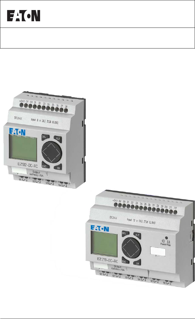
OverviewFor more information visit: www.EatonElectrical.comMN05013003E 15Models EZ basic units at a glanceFigure 2: Models Power supply Inputs
For more information visit: www.EatonElectrical.comWiring with EZMN05013003E186Example circuits Star-delta startingYou can implement two star-delta ci
Example circuitsFor more information visit: www.EatonElectrical.comMN05013003E 187Figure 75: Star-delta circuit with EZ1122Q1I1LNQ2K3MK5MK1MNK1MLNS1S2
For more information visit: www.EatonElectrical.comWiring with EZMN05013003E188Function of the EZ circuit diagram:Start/stop of the circuit with the e
Example circuitsFor more information visit: www.EatonElectrical.comMN05013003E 189Table 26: Shift registerAssign the information “bad” to value 0. If
For more information visit: www.EatonElectrical.comWiring with EZMN05013003E190Figure 77: EZ circuit diagram shift registerHow does the shift register
Example circuitsFor more information visit: www.EatonElectrical.comMN05013003E 191In the second cycle break contact M7 is open. The series circuit is
For more information visit: www.EatonElectrical.comWiring with EZMN05013003E192How are all the storage locations cleared?When I3 is activated, all the
Example circuitsFor more information visit: www.EatonElectrical.comMN05013003E 193Figure 78: EZ run light circuit diagramFlasher relayGenerate shift p
For more information visit: www.EatonElectrical.comWiring with EZMN05013003E194Stairwell lightingFor a conventional circuit you would need at least fi
Example circuitsFor more information visit: www.EatonElectrical.comMN05013003E 195Figure 80: Stairwell lighting with EZButton pressed brieflyLight ON
EZ500_700.book Page 2 Tuesday, May 3, 2005 5:15 PM
For more information visit: www.EatonElectrical.comEZMN05013003E16EZ basic units with stand-alone EZD-80.., EZD-CP4-500 HMI unitFigure 3: Overview wi
For more information visit: www.EatonElectrical.comWiring with EZMN05013003E196Figure 81: EZ circuit diagram stairwell lightingMeaning of the contacts
Example circuitsFor more information visit: www.EatonElectrical.comMN05013003E 197If you use an EZ with analog inputs, you can optimize the stairwell
EZ500_700.book Page 198 Tuesday, May 3, 2005 5:15 PM
For more information visit: www.EatonElectrical.com 199MN05013003E5 EZ SettingsSettings can only be carried out on EZ models provided with buttons and
For more information visit: www.EatonElectrical.comEZ SettingsMN05013003E200Password setupA password can be set up via the System menu in either RUN o
Password protectionFor more information visit: www.EatonElectrical.comMN05013003E 201Selecting the scope of the passwordXPress the OK button.XSelect t
For more information visit: www.EatonElectrical.comEZ SettingsMN05013003E202Activating the passwordYou can activate a valid password in three differen
Password protectionFor more information visit: www.EatonElectrical.comMN05013003E 203Unlocking EZUnlocking EZ will deactivate the password. You can re
For more information visit: www.EatonElectrical.comEZ SettingsMN05013003E204Changing or deleting the password rangeXUnlock EZ.XPress DEL and ALT to ca
Changing the menu languageFor more information visit: www.EatonElectrical.comMN05013003E 205After the fourth entry attempt EZ will ask whether you wis
OverviewFor more information visit: www.EatonElectrical.comMN05013003E 17Type referenceEZ xxx-xx-xxxLCD display: X = No displayTime switch: C = Availa
For more information visit: www.EatonElectrical.comEZ SettingsMN05013003E206XPress DEL and ALT to call up the System menu.XSelect LANGUAGE… to change
Changing parametersFor more information visit: www.EatonElectrical.comMN05013003E 207All function relays are displayed as a list.The following precond
For more information visit: www.EatonElectrical.comEZ SettingsMN05013003E208In RUN mode EZ operates with a new setpoint as soon as it has been modifie
Setting date, time and daylight savingFor more information visit: www.EatonElectrical.comMN05013003E 209XSet the switching off time to 22:00.XPress OK
For more information visit: www.EatonElectrical.comEZ SettingsMN05013003E210XSet the values for time, day, month and year.XPress the OK button to acce
Setting date, time and daylight savingFor more information visit: www.EatonElectrical.comMN05013003E 211This will open the menu for setting the time.X
For more information visit: www.EatonElectrical.comEZ SettingsMN05013003E212The following rules normally apply:Table 27: DST setting ruleWhen Weekday
Setting date, time and daylight savingFor more information visit: www.EatonElectrical.comMN05013003E 213Table 28: Date parametersExample with EU (Euro
For more information visit: www.EatonElectrical.comEZ SettingsMN05013003E214Table 30: EU summer time startThe following start and times for summer tim
Setting date, time and daylight savingFor more information visit: www.EatonElectrical.comMN05013003E 2151) Relevant local time to which the clock shou
For more information visit: www.EatonElectrical.comEZMN05013003E18EZ operation ButtonsMoving through menus and choosing valuesDEL: Delete object in c
For more information visit: www.EatonElectrical.comEZ SettingsMN05013003E216The two SUMMER START (start of summer time) and SUMMER END (end of summer
Setting date, time and daylight savingFor more information visit: www.EatonElectrical.comMN05013003E 217XPress the OK button to access the Entry mode.
For more information visit: www.EatonElectrical.comEZ SettingsMN05013003E218Activating debounce (input delay)Input signals can be evaluated by EZ with
Activating debounce (input delay)For more information visit: www.EatonElectrical.comMN05013003E 219The input delay (debounce) is set with the DEBOUNCE
For more information visit: www.EatonElectrical.comEZ SettingsMN05013003E220Activating and deactivating the P buttonsEven though the cursor buttons (P
Startup behaviorFor more information visit: www.EatonElectrical.comMN05013003E 221Deactivating the P buttonsXSelect P BUTTONS å and press OK.EZ change
For more information visit: www.EatonElectrical.comEZ SettingsMN05013003E222Activating RUN modeDisplayed as EZ RUNMODE å, this means that EZ will star
Startup behaviorFor more information visit: www.EatonElectrical.comMN05013003E 223Possible faultsEZ will not start in RUN mode:• EZ does not contain a
For more information visit: www.EatonElectrical.comEZ SettingsMN05013003E224Deactivating card modeXSelect CARD MODE å and press the OK button.The Card
Setting the cycle timeFor more information visit: www.EatonElectrical.comMN05013003E 225Setting the cycle time EZ allows you to fix the cycle time. To
OverviewFor more information visit: www.EatonElectrical.comMN05013003E 19Selecting main and system menuStatus display1.2RSMO.2 6..I .2..5...P-MO 02:
For more information visit: www.EatonElectrical.comEZ SettingsMN05013003E226Retention (non-volatile data storage)It is a requirement of system and mac
Retention (non-volatile data storage)For more information visit: www.EatonElectrical.comMN05013003E 227XSwitch to STOP mode.XSwitch to the System menu
For more information visit: www.EatonElectrical.comEZ SettingsMN05013003E228Deleting retentive actual valuesThe retentive actual values are cleared if
Retention (non-volatile data storage)For more information visit: www.EatonElectrical.comMN05013003E 229Changing the operating mode or the circuit diag
For more information visit: www.EatonElectrical.comEZ SettingsMN05013003E230Displaying device informationDevice information is provided for service ta
For more information visit: www.EatonElectrical.com 231MN05013003E6Inside EZEZ circuit diagram cycle In conventional control systems, a relay or conta
For more information visit: www.EatonElectrical.comInside EZMN05013003E232The fifth segment is outside the circuit diagram and EZ uses it to establish
EZ circuit diagram cycleFor more information visit: www.EatonElectrical.comMN05013003E 233Example: switching in the next cycle Start condition:• I1, I
For more information visit: www.EatonElectrical.comInside EZMN05013003E234Delay times for inputs and outputsThe time from reading the inputs and outpu
Delay times for inputs and outputsFor more information visit: www.EatonElectrical.comMN05013003E 235An input signal S1 must therefore be 15 V or 8 V (
For more information visit: www.EatonElectrical.comEZMN05013003E20Toggling between weekday, time display and date display(only on devices with clock)
For more information visit: www.EatonElectrical.comInside EZMN05013003E236Delay time with EZ-AB, EZ-AC basic unitsThe input delay with AC voltage sign
Delay times for inputs and outputsFor more information visit: www.EatonElectrical.comMN05013003E 237If a button or switch bounces (A), the delay time
For more information visit: www.EatonElectrical.comInside EZMN05013003E238Monitoring of short-circuit/overload with EZ..-D.-T..Depending on the type o
Expanding EZ700For more information visit: www.EatonElectrical.comMN05013003E 239Example 3: Automatic reset of error signalThe circuit diagram functio
For more information visit: www.EatonElectrical.comInside EZMN05013003E240These modules offer considerably more functions than simple I/O expansion mo
Expanding EZ700For more information visit: www.EatonElectrical.comMN05013003E 241Function monitoring of expansion unitsIf the power supply of the expa
For more information visit: www.EatonElectrical.comInside EZMN05013003E242Example with LCD output and reset of the outputsSaving and loading circuit d
Saving and loading circuit diagramsFor more information visit: www.EatonElectrical.comMN05013003E 243Figure 88: Do not touch the interfaceXCarefully r
For more information visit: www.EatonElectrical.comInside EZMN05013003E244Memory card The card is available as an accessory EZ-M-32K for EZ500 and EZ7
Memory cardFor more information visit: www.EatonElectrical.comMN05013003E 245Loading or saving circuit diagramsYou can only transfer circuit diagrams
OverviewFor more information visit: www.EatonElectrical.comMN05013003E 21Advanced Status displayEZ LED displayEZ512-..-..X, EZ700 and EZ-E feature an
For more information visit: www.EatonElectrical.comInside EZMN05013003E246EZ-M-32KXSwitch to STOP mode.XSelect PROGRAM… from the main menu.XSelect the
Memory cardFor more information visit: www.EatonElectrical.comMN05013003E 247Loading a circuit diagram from the cardXSelect the CARD J DEVICE menu opt
For more information visit: www.EatonElectrical.comInside EZMN05013003E248EZSoft EZSoft is a PC program with which you can create, store, test (simula
Overview with stand-alone displayFor more information visit: www.EatonElectrical.comMN05013003E 249If there are transmission problems, EZ will displa
For more information visit: www.EatonElectrical.comInside EZMN05013003E250If a display/operating unit with a keypad is used, EZ can be programmed and
For more information visit: www.EatonElectrical.com 251MN05013003E7 What Happens If ...?You may sometimes find that EZ does not do exactly what you ex
For more information visit: www.EatonElectrical.comWhat Happens If ...?MN05013003E252Possible situations when creating circuit diagramsERROR: CLOCK Cl
Possible situations when creating circuitFor more information visit: www.EatonElectrical.comMN05013003E 253Input not detected Loose terminal contact C
For more information visit: www.EatonElectrical.comWhat Happens If ...?MN05013003E254EventEvent Explanation RemedyThe actual values are not being stor
For more information visit: www.EatonElectrical.com 255MN05013003EAppendixDimensionsFigure 94: Dimensions of EZ200 in mm (for dimensions in inches see
For more information visit: www.EatonElectrical.comEZMN05013003E22Menu structureMain menu without password protectionXYou access the main menu by pre
For more information visit: www.EatonElectrical.comAppendixMN05013003E256Figure 95: Dimensions of EZ512-… in mm (for dimensions in inches see page 257
DimensionsFor more information visit: www.EatonElectrical.comMN05013003E 257Figure 96: Dimensions of EZ700 in mm (for dimensions in inches see table 3
For more information visit: www.EatonElectrical.comAppendixMN05013003E258Technical Data GeneralEZ…EZ200 EZ512 EZ700Dimensions W × H × D [mm] 35.5 × 90
Technical DataFor more information visit: www.EatonElectrical.comMN05013003E 259Oscillations (IEC 60068-2-6) 10 to 57 Hz (constant amplitude 0.15 mm)5
For more information visit: www.EatonElectrical.comAppendixMN05013003E260Special approvalsBackup/accuracy of real-time clock (only with EZ-C)Clock bat
Technical DataFor more information visit: www.EatonElectrical.comMN05013003E 261Power supplyEZ512-AC-…, EZ719-AC-…, EZ512-AB-…, EZ719-AB-…EZ512-DA-…,
For more information visit: www.EatonElectrical.comAppendixMN05013003E262InputsEZ-512-AB-…, EZ719-AB-…Voltage dips 10 ms, IEC/EN 61131-2Power lossEZ51
Technical DataFor more information visit: www.EatonElectrical.comMN05013003E 263EZ-512-AC-…, EZ618-AC-.E, EZ719-AC-…Delay time for 0 to 1 and 1 to 0 f
For more information visit: www.EatonElectrical.comAppendixMN05013003E264EZ512-DA-…, EZ719-DA-...Input current with 1 signalR1 to R12, I1 to I6 (EZ71.
Technical DataFor more information visit: www.EatonElectrical.comMN05013003E 265EZ512-DC-…, EZ6..-DC-.E, EZ7..-DC--Status display LCD (if provided) LC
OverviewFor more information visit: www.EatonElectrical.comMN05013003E 23PROGRAM...ÆSTOP RUN åPARAMETERINFO... æSET CLOCK..Main menuParameter display
For more information visit: www.EatonElectrical.comAppendixMN05013003E266Status display LCD (if provided)Electrical isolationTo power supply No No NoB
Technical DataFor more information visit: www.EatonElectrical.comMN05013003E 267High-speed counter inputs, I1 to I4 EZ512-DA-…, EZ512-DC-…, EZ719-DA-…
For more information visit: www.EatonElectrical.comAppendixMN05013003E268Relay outputsEZ512-..-R…, EZ618-..-RE/EZ719-..-R.., EZ202-REConversion time,
Technical DataFor more information visit: www.EatonElectrical.comMN05013003E 269Rated operational voltage Ue250 V ACSafe isolation to EN 50178 between
For more information visit: www.EatonElectrical.comAppendixMN05013003E270UL/CSATransistor outputsEZ-512-D.-T…, EZ620-DC-.E, EZ72…Uninterrupted current
Technical DataFor more information visit: www.EatonElectrical.comMN05013003E 271Residual current at state 0 per channel < 0.1 mA < 0.1 mAMax. ou
For more information visit: www.EatonElectrical.comAppendixMN05013003E272Inductive load (without external suppressor circuit)General explanations: T0.
List of the function relaysFor more information visit: www.EatonElectrical.comMN05013003E 273List of the function relays Usable contactsT0.95 = 15 msR
For more information visit: www.EatonElectrical.comAppendixMN05013003E274Available function relaysEZ output Q q Q1…Q4 Q1…Q8 81Expansion input terminal
List of the function relaysFor more information visit: www.EatonElectrical.comMN05013003E 275Names of relaysNames of function relayConditional jump :
For more information visit: www.EatonElectrical.comEZMN05013003E24AM --ÆWD: ----DD.MM:00.00æHH:MM:00:00DIFF: 0:00NONE ÆRULE... åEUGB æUSNONE ÆRULE..
For more information visit: www.EatonElectrical.comAppendixMN05013003E276Name of function block inputs (constants, operands)Memory card attributesInpu
For more information visit: www.EatonElectrical.com 277MN05013003EGlossaryAnalog input The device EZ-AB, EZ-DA and EZ-DC are provided with the two (EZ
For more information visit: www.EatonElectrical.comGlossaryMN05013003E278Impulse relay An impulse relay is a relay which changes its switching state a
For more information visit: www.EatonElectrical.comMN05013003E 279Operating buttons EZ has eight operating buttons. These are used to select menu func
For more information visit: www.EatonElectrical.comGlossaryMN05013003E280Remote expansion I/O expansion with the expansion unit (e.g. EZ620-DC-TE) ins
For more information visit: www.EatonElectrical.com 281MN05013003EIndex7-day time switchCompatibility of parameters ...282A Amb
For more information visit: www.EatonElectrical.comIndexMN05013003E282Buttons ...18But
For more information visit: www.EatonElectrical.comMN05013003E 283Coil functionContactor ...90Imp
For more information visit: www.EatonElectrical.comIndexMN05013003E284Connecting DC voltage ...35Connecting fre
For more information visit: www.EatonElectrical.comMN05013003E 285CurrentInput ...39, 44Input c
OverviewFor more information visit: www.EatonElectrical.comMN05013003E 25Main menu with password protectionEZ System menuThe System menu is accessed b
For more information visit: www.EatonElectrical.comIndexMN05013003E286Example circuits ...186Expanding
For more information visit: www.EatonElectrical.comMN05013003E 287I Improper use ...11Impulse r
For more information visit: www.EatonElectrical.comIndexMN05013003E288M Main menuOverview ...22S
For more information visit: www.EatonElectrical.comMN05013003E 289O Operating buttons ...73, 279Operating hour
For more information visit: www.EatonElectrical.comIndexMN05013003E290P P buttons ...279Act
For more information visit: www.EatonElectrical.comMN05013003E 291R Reaction time for I/O ...240Reed relay co
For more information visit: www.EatonElectrical.comIndexMN05013003E292Rungs ...280Add
For more information visit: www.EatonElectrical.comMN05013003E 293T Target readership ...11Technical d
For more information visit: www.EatonElectrical.comIndexMN05013003E294V Value entry ...18Vol
EZ500_700.book Page 1 Tuesday, May 3, 2005 5:15 PM
For more information visit: www.EatonElectrical.comMN05013003E IBefore commencing the installation• Disconnect the power supply of the device.• Ensure
For more information visit: www.EatonElectrical.comEZMN05013003E26DEBOUNCE åP-BUTTONSRUN MODE åCARD MODEENGLISH ÆDEUTSCH åFRANCAISESPANOL æITALIANOPO
© 2005 Eaton CorporationAll Rights ReservedPrinted in USAPublication No. MN05013003EApril 2005Eaton Electrical1000 Cherrington ParkwayMoon Township, P
OverviewFor more information visit: www.EatonElectrical.comMN05013003E 27Selecting or toggling between menu itemsCursor displayCursor Í ÚSelect or tog
For more information visit: www.EatonElectrical.comEZMN05013003E28Setting valuesSelect value Í ÚSelect digit úíChange value at digit ÍÚStore entriesR
For more information visit: www.EatonElectrical.com 29MN05013003E2InstallationEZ must only be installed and wired up by trained electricians or other
For more information visit: www.EatonElectrical.comInstallationMN05013003E30For ease of wiring, leave a gap of at least 30 mm between EZ terminals and
MountingFor more information visit: www.EatonElectrical.comMN05013003E 31Using a mounting plateMounting on a mounting plate requires the use of fixing
For more information visit: www.EatonElectrical.comInstallationMN05013003E32Connecting the expansion deviceFigure 3: Connecting expansion units1342EZ5
TerminalsFor more information visit: www.EatonElectrical.comMN05013003E 33XOpen the EZ-LINK connections on the side of both EZ devices.XFit the EZ-LIN
For more information visit: www.EatonElectrical.comInstallationMN05013003E34Supplying AC unitsSupplying AC basic unitsEZ…-AB-RC(RCX), EZ…-AC-R(RC, RCX
Connecting the power supplyFor more information visit: www.EatonElectrical.comMN05013003E 35Supplying DC unitsSupplying DC basic unitsEZ…-DA-RC(X), EZ
MN05013004E For more information visit: www.EatonElectrical.com MN05013003EII• Devices that are designed for mounting in housings or control cabinets
For more information visit: www.EatonElectrical.comInstallationMN05013003E36Supplying DC expansion unitsEZ…-DC-.EFigure 7: Power supply on the DC expa
Connecting the inputsFor more information visit: www.EatonElectrical.comMN05013003E 37Connecting the inputs EZ inputs switch electronically. Once you
For more information visit: www.EatonElectrical.comInstallationMN05013003E38Connecting EZ AC digital inputs on the basic unitFigure 9: Connecting EZ-A
Connecting the inputsFor more information visit: www.EatonElectrical.comMN05013003E 39Table 1: EZ-AB input signal valuesTable 2: EZ-AC input signalsCa
For more information visit: www.EatonElectrical.comInstallationMN05013003E40For longer lengths connect in series a diode (e.g. 1N4007) for 1 A, min. 1
Connecting the inputsFor more information visit: www.EatonElectrical.comMN05013003E 41Increasing the input currentThe following input circuit can be u
For more information visit: www.EatonElectrical.comInstallationMN05013003E42Complete devices for increasing the input current are available under the
Connecting the inputsFor more information visit: www.EatonElectrical.comMN05013003E 43Connecting DC digital inputs on the basic unitFigure 15: Connect
For more information visit: www.EatonElectrical.comInstallationMN05013003E44Table 3: EZ-DC input signalsTable 4: EZ-DA input signalsConnecting EZ DC a
Connecting the inputsFor more information visit: www.EatonElectrical.comMN05013003E 45Safety measures with analog signalsXUse shielded twisted pair ca
For more information visit: www.EatonElectrical.comMN05013003E 1About This Manual 9Device designation 9Writing conventions 101EZ 11Target readershi
For more information visit: www.EatonElectrical.comInstallationMN05013003E46Power supply of EZ-AB devices and analog inputsWith EZ-AB devices that pro
Connecting the inputsFor more information visit: www.EatonElectrical.comMN05013003E 47Analog setpoint potentiometer, EZ-AB, EZ-DA, EZ-DCFigure 18: Ana
For more information visit: www.EatonElectrical.comInstallationMN05013003E48Brightness sensor, EZ-AB, EZ-DA, EZ-DCFigure 20: Connection of a brightnes
Connecting the inputsFor more information visit: www.EatonElectrical.comMN05013003E 4920 mA sensor4 to 20 mA (0 to 20 mA) sensors can be connected eas
For more information visit: www.EatonElectrical.comInstallationMN05013003E50• I3 = C15 frequency counter• I4 = C16 frequency counterPulse shape of cou
Connecting the outputsFor more information visit: www.EatonElectrical.comMN05013003E 51Connecting the outputs The Q outputs function inside EZ as isol
For more information visit: www.EatonElectrical.comInstallationMN05013003E52Connecting relay outputsEZ512-..-R..Figure 25: EZ512-..-R.. relay outputsF
Connecting the outputsFor more information visit: www.EatonElectrical.comMN05013003E 53EZ618-..-REFigure 27: EZ618-..-RE.. relay outputsUnlike the inp
For more information visit: www.EatonElectrical.comInstallationMN05013003E54Connecting transistor outputsEZ512-..-T..Figure 28: EZ512-..-T.. transisto
Connecting the outputsFor more information visit: www.EatonElectrical.comMN05013003E 55EZ620-..-TEFigure 30: EZ620-..-TE transistor outputsParallel co
For more information visit: www.EatonElectrical.com MN05013003E22 Installation 29Mounting 29Connecting the expansion device 32Terminals 33– Tools 33–
For more information visit: www.EatonElectrical.comInstallationMN05013003E56If inductive loads are not suppressed, the following applies: Several indu
Expanding inputs/outputsFor more information visit: www.EatonElectrical.comMN05013003E 57Expanding inputs/outputs You can add expansion units to the f
For more information visit: www.EatonElectrical.comInstallationMN05013003E58Remote expansionRemote expansion units can be installed and run up to 30 m
Expanding inputs/outputsFor more information visit: www.EatonElectrical.comMN05013003E 59Figure 33: Connecting remote expansion units to EZE+ E–E+ E–E
For more information visit: www.EatonElectrical.comInstallationMN05013003E60Connecting bus systems The EZ-LINK connection is designed to allow bus con
Switching onFor more information visit: www.EatonElectrical.comMN05013003E 613 CommissioningSwitching on Before switching on EZ, check that you have c
For more information visit: www.EatonElectrical.comCommissioningMN05013003E62Setting the menu language When you switch on EZ for the first time, you w
EZ operating modesFor more information visit: www.EatonElectrical.comMN05013003E 63EZ operating modes EZ has two operating modes - RUN and
For more information visit: www.EatonElectrical.comCommissioningMN05013003E64Creating your first circuit diagramThe following small circuit diagram ta
Creating your first circuit diagramFor more information visit: www.EatonElectrical.comMN05013003E 65Figure 2: Lamp controller with EZStarting point: t
For more information visit: www.EatonElectrical.comMN05013003E 34 Wiring with EZ 73Operation of EZ 73– Buttons for editing circuit diagrams and func
For more information visit: www.EatonElectrical.comCommissioningMN05013003E66XPress OK to switch to the main menu.Press OK to switch to the next menu
For more information visit: www.EatonElectrical.comMN05013003E 67From the first contact to the output coilWith EZ, you work from the input to the outp
For more information visit: www.EatonElectrical.comCommissioningMN05013003E68WiringEZ displays a small arrow in the circuit diagram for creating the w
For more information visit: www.EatonElectrical.comMN05013003E 69XPress OK.EZ will insert relay coil Q1. The specified coil function Ä and the output
For more information visit: www.EatonElectrical.comCommissioningMN05013003E70XPress OK.The tick changes to STOP RUN åThe Status display shows the cur
For more information visit: www.EatonElectrical.comMN05013003E 71Deleting the circuit diagramXSwitch EZ to STOP mode.The display shows STOP å RUN.XUse
EZ500_700.book Page 72 Tuesday, May 3, 2005 5:15 PM
For more information visit: www.EatonElectrical.com 73MN05013003E4 Wiring with EZBy working through the example in chapter 3 you should now have gaine
For more information visit: www.EatonElectrical.comWiring with EZMN05013003E74OperationThe cursor buttons in the EZ circuit diagram perform three func
Operation of EZFor more information visit: www.EatonElectrical.comMN05013003E 75Circuit diagramThe circuit diagram is that part of the program where t
For more information visit: www.EatonElectrical.com MN05013003E47-day time switch 140– Parameter display and parameter set for 7-day time switch: 14
For more information visit: www.EatonElectrical.comWiring with EZMN05013003E76CoilsCoils are the actuating mechanisms of relays. In RUN mode, the resu
Operation of EZFor more information visit: www.EatonElectrical.comMN05013003E 77Relay, function relaysEZ has nine different types of relay for wiring
For more information visit: www.EatonElectrical.comWiring with EZMN05013003E78You can set the switching behavior of these relays by means of the coil
Operation of EZFor more information visit: www.EatonElectrical.comMN05013003E 79• Connections are used to produce the electrical contact between switc
For more information visit: www.EatonElectrical.comWiring with EZMN05013003E80Saving and loading circuit diagramsThere are two ways of saving circuit
Working with contacts and relaysFor more information visit: www.EatonElectrical.comMN05013003E 81Input and output contactsFirst specify which input an
For more information visit: www.EatonElectrical.comWiring with EZMN05013003E82Values for contacts and coil fields are changed in Entry mode. The value
Working with contacts and relaysFor more information visit: www.EatonElectrical.comMN05013003E 83EZ will leave Entry mode when you press úí or OK to l
For more information visit: www.EatonElectrical.comWiring with EZMN05013003E84XSwitch to Entry mode and move the cursor over the contact name.XPress A
Working with contacts and relaysFor more information visit: www.EatonElectrical.comMN05013003E 85Never work backwards. You will learn why wiring backw
For more information visit: www.EatonElectrical.comMN05013003E 5Basic circuits 178– Negation (contact) 178– Negation (coil) 179– Maintained contact
For more information visit: www.EatonElectrical.comWiring with EZMN05013003E86Inserting and deleting a rungThe EZ circuit diagram shows four of the 12
Working with contacts and relaysFor more information visit: www.EatonElectrical.comMN05013003E 87Switching with the cursor buttonsWith EZ, you can als
For more information visit: www.EatonElectrical.comWiring with EZMN05013003E88Checking the circuit diagramEZ contains a built-in measuring device enab
Working with contacts and relaysFor more information visit: www.EatonElectrical.comMN05013003E 89Coil functionsYou can set the coil function to determ
For more information visit: www.EatonElectrical.comWiring with EZMN05013003E90Rules for wiring relay coilsTo ensure a clear overview of all relay stat
Working with contacts and relaysFor more information visit: www.EatonElectrical.comMN05013003E 91Contactor function with negated result (inverse conta
For more information visit: www.EatonElectrical.comWiring with EZMN05013003E92Representation in EZ:•Markers M, N: èM1 to èM16, èN1 to èN16• Jumps: è:1
Working with contacts and relaysFor more information visit: www.EatonElectrical.comMN05013003E 93Impulse relay äThe relay coil switches whenever the i
For more information visit: www.EatonElectrical.comWiring with EZMN05013003E94Latching relayThe “latch” and “unlatch” relay functions are used in pair
Function relaysFor more information visit: www.EatonElectrical.comMN05013003E 95Function relays Function relays allow you to simulate the functions of
More documents for Networking Eaton PROFIBUS-DP EZ204-DP


Related products and manuals for Networking Eaton PROFIBUS-DP EZ204-DP
 (11 pages)
(12 pages)
(64 pages)
(14 pages)
(11 pages)
(12 pages)
(64 pages)
(14 pages)
© 2020, manymanuals.com. All rights reserved. | 0.903 s |
 Manymanuals.com
 Manymanuals.de
 Manymanuals.fr
 Manymanuals.it
 Manymanuals.pl
 Manymanuals.cz
 Manymanuals.es
 Manymanuals-pt.com
Comments to this Manuals